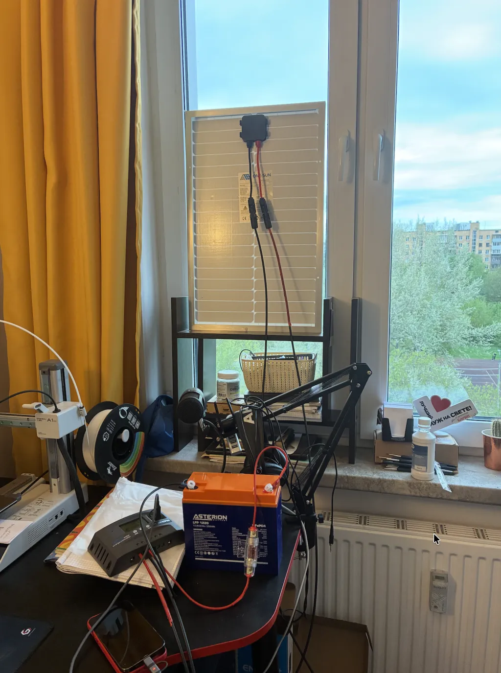
I’m currently building a DIY smart home ecosystem on a Raspberry Pi. At some point, it just clicked: why not power the whole thing with solar energy? So, I ordered everything I needed from Ozon: a 50W solar panel, an MPPT charge controller, a 20Ah LiFePO4 battery, an inverter, MC4 cables, and a fuse holder.
I’m currently building a DIY smart home ecosystem on a Raspberry Pi. At some point, it just clicked: why not power the whole thing with solar energy?
So, I ordered everything I needed from Ozon: a 50W solar panel, an MPPT charge controller, a 20Ah LiFePO4 battery, an inverter, MC4 cables, and a fuse holder.
What I Underestimated
Between "I have the hardware" and "the system actually works" lies a massive layer of nuances that nobody really writes about. Or rather, they do write about them, but in ten different places. Until you trip over these traps yourself, you won’t even understand what they were warning you about.
- Example 1: Alligator clips. The battery came with alligator clips. Okay, I clip the positive one on, and the controller should come to life. But under load, alligator clips heat up, oxidize, and can easily slip off. Sure, it’s fine for a 5-minute bench test, but definitely not for a system meant to run 24/7. You need proper wiring, ring terminals, and a crimping tool to do it right.
- Example 2: The 40A fuse. The included fuse was rated for 40 Amps. However, my 2.5 mm² wire can only handle 25A continuously. This means that in the event of a short circuit, the wire would melt long before the fuse even thought about blowing. I went ahead and bought a 20A blade fuse instead.
- Example 3: The battery manual vs. reality. The battery datasheet specified "M4 terminals, 4 $N\cdot m$ torque." Perfect, I ordered M4 ring terminals. I unbox the battery, and surprise—it has M5 studs. The manual turned out to be generic for the entire product line, failing to reflect the actual model. I had to drill out the terminals to make them fit.
Configuring the Controller
My controller is a POWERWIN MT50. The display features three buttons and a bunch of icons. The paper manual listed only three main parameters: HVD (High Voltage Disconnect), LVR (Low Voltage Reconnect), and LVD (Low Voltage Disconnect). You adjust the numbers while the value flashes, increase it with the arrow button, and confirm.
The default settings were configured for a lead-acid battery. Mine is a LiFePO4. That’s not a complete disaster—the default 14.2V HVD is perfectly safe for lithium. However, the LVD was set to 10.7V, whereas you shouldn't discharge a LiFePO4 battery below 11.0V without damaging it. So, I bumped it up.
The menu also features b1, b2, and b3 profiles, with absolutely zero explanation in the manual. I left it on b1 and adjusted the parameters manually.
Connecting the Panel
The panel connects via two MC4 connectors. The 4-meter extension cables had MC4 connectors on both ends. To wire them into the controller’s screw terminals, you need bare wire, not a connector. Instead of cutting them off, I disassembled the MC4 housings (unscrewed the nut, pulled out the pin, and exposed the wire). This way, I saved the connector shells for the future while getting the bare wire I needed.
I verified the polarity using a multimeter. This was the final step where I could have fried everything. It read 16V on the free ends, with the positive lead matching the red marking—all good. I connected the negative terminal first, then the positive, and angled the panel toward the window.
The controller screen displayed 0 Amps of charging current. For a second, I thought something was broken. In reality, the battery was just completely full, so the controller had nowhere to send the power. I plugged my phone into the USB port, the battery voltage dropped slightly, and the panel immediately started compensating.
Lessons Learned
- Documentation lies or leaves things out. The battery datasheet gave the wrong thread size. The controller manual ignored half the menu. The product page showed one type of fuse holder, but a completely different one arrived. This is just the nature of the DIY segment: sellers buy in bulk from China, print datasheets "by the chart," and grab photos straight from AliExpress. You have to double-check everything yourself.
- AI is a great assistant, but a terrible authority. I cross-checked info with ChatGPT and Claude multiple times, and both hallucinated confidently on specific details. One insisted that
b3stands for LFP; another confused a compression fuse holder with a screw-type one. When you see a confident answer from an AI, always double-check it with actual documentation—ideally the paper manual inside the box. - "Negative first, then positive" is not a superstition. It’s a real safeguard against accidentally shorting the circuit with your tools.
- The most valuable investment isn't hardware—it's a pause. When you're about to plug in that last wire to close the circuit and a sudden doubt hits you: don't rush. Put the wire down. Step back. Look at your schematic one more time. Figure out where your "panic button" is if something goes sideways. Only then do you plug it in.
What’s Next?
The MVP (Minimum Viable Product) is up and running on my desk. The battery holds all the settings, the panel delivers current, and the controller monitors everything. Next steps:
- Move the system to its permanent spot. Build a shelf for the battery and controller. Mount the panel outside on the window sill at a 30–40 degree angle, running the cable through the window frame.
- Connect an INA219 current sensor to the Raspberry Pi. This will feed real Watt-hour data into my dashboard, rather than relying solely on the controller's screen.
- Power the Raspberry Pi directly from the controller’s USB output. This is the ultimate goal: a self-sustaining home server.
- Install the smoke detector and fire extinguisher. They are already bought, but the detector still needs to be mounted. Better safe than sorry.
The Takeaway
The goal here wasn't to take my entire apartment off the grid. The goal was to understand how this works at a low level. To take it apart, crimp the wires, measure it with a multimeter, mess up, and rebuild it.
In a world where more and more "smart" devices are locked behind proprietary apps, having the hands to build something like this from scratch is a small, sovereign pleasure. Highly recommended.
Comments
Sign in to leave a comment. sign in